Series Resonant Converter Design
Resonant converters, especially the LLC series resonant converter (LLC-SRC) in Figure 1, have become popular over the last decade.Figure 1. Half-bridge LLC series resonant converter.When compared to, LLC-SRC provides the following advantages:.
Lower component counts. Higher converter efficiency.
Lower conduction/radiation electromagnetic interference (EMI). Low voltage stress on all circuit switchesAll these benefits seem great, but when you realize its is so complex you might think“Wait a minute!

There are more than two variables in the gain equation! I’m not going to do that.”Don’t give up so fast. It only takes a few minutes to walk through this blog and understand how to play with LLC-SRC. You just need to figure out how to determine the transformer turns ratio and resonant tank parameters.Let’s get over your fear of the voltage gain equation first.
Series Resonant Converter Design For Beginners
LLC-SRC has 50% duty cycles on its primary switches to generate a square wave at the input of its resonant tank. By applying, LLC-SRC can be simplified to the following linear circuit:Figure 2. Linearized LLC series resonant converter.The voltage gain equation is derived from this linear circuit, but let’s ignore that “hard to memorize” equation for now. It’s notable that LLC-SRC efficiency is optimized when the switching frequency f s is equal to the resonant frequency f r. When fs=fr, the series connected LC becomes zero impedance, and the above linear circuit becomes Figure 3 below.Figure 3.
Linearized LLC series resonant converter at f s=f r.Input voltage and current are now in phase, and there is no reactive power dissipated in the circuit. Now the input/output voltage gain becomesIn short, you just need to design your transformer turns ratio with the equation above at the input voltage you want your converter efficiency optimized.When it comes to the resonant tank parameter (L r, L m, and C s) design, many trade-offs need to be made. Let’s not confuse you with all these trade-offs. An easy way to start your resonant tank parameter design is to start with our LLC-SRC reference designs. For example, has L r=72µH, L m350µH, and C r=0.033 µF and is designed for 240W output power with 280V to 400V input voltage range. Alright, we get all the resonant tank details of a 240W LLC-SRC design.
Archivos Root Explorer v2.16 Otro software para Android. Image thumbnails, APK binary XML viewer, change file owner and group.  With root explorer you can easily Access the complete android's file system including. Root Explorer v2.2.3 Apk screenshots. V.1.0November 16,2017. Root Explorer is the ultimate file manager for root users. Access the whole of android's file system (including the elusive data folder!).Features include multiple. Root Explorer poster Root Explorer screenshot 1 Root Explorer screenshot 2 Root Explorer screenshot 3 Root Explorer screenshot 4 Root Explorer screenshot 5.
Where should we go from this point? It’s easy; just remember the following key tips for tuning up resonant tank parameters:. Higher L m/L r ratio leads to a narrower regulation range (Input or output). Higher L r/C r ratio leads to worse load regulation and narrower regulation range.If your LLC-SRC needs to operate in a wider input voltage range, you need a lower L m/L r ratio.
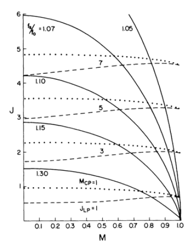
If you are designing your LLC-SRC to function at a higher power level, you need a lower L r/C r ratio. Once you have your new resonant tank parameters, check them with the gain curve under different input voltages at full load to make sure the gain is high enough to provide the output voltage you need. The PMP5141 LLC-SRC gain curves below show that under 280V to 400V input voltages, I have enough gain to provide 24V output voltages at 240W load.See, it’s not that hard! Now you should feel more comfortable with a LLC-SRC design. Visit TI Designs to discover more LLC-SRC reference designs. Some LLC-SRC design examples are shown in the list below:.
– Two stage PSU, 42V/6A output. – 295VDC-400VDC Input, 12V/460W output. – Two stage PSU, 290VDC-400VDC Input at LLC-SRC, 56V/100W output. – Two stage PSU, 290VDC-400VDC Input at LLC-SRC, 12V/100W output.
Hi,For typical application where input is 53VAC to 90AVC (60Vpk to 132Vpk) and output is 43VDC (300W design), i am trying to design single stage LLC HF Bridge topology using UCC25600.After reading LLC related blogs and looking at input voltage variation I need to consider Lm/Lr low 3 4 (?). But input to output voltage conversion at low line input gives me transformer turns ratio n 1.What could be the situation if n.
All content and materials on this site are provided 'as is'. TI and its respective suppliers and providers of content make no representations about the suitability of these materials for any purpose and disclaim all warranties and conditions with regard to these materials, including but not limited to all implied warranties and conditions of merchantability, fitness for a particular purpose, title and non-infringement of any third party intellectual property right. No license, either express or implied, by estoppel or otherwise, is granted by TI. Use of the information on this site may require a license from a third party, or a license from TI.Content on this site may contain or be subject to specific guidelines or limitations on use. All postings and use of the content on this site are subject to the of the site; third parties using this content agree to abide by any limitations or guidelines and to comply with the of this site. TI, its suppliers and providers of content reserve the right to make corrections, deletions, modifications, enhancements, improvements and other changes to the content and materials, its products, programs and services at any time or to move or discontinue any content, products, programs, or services without notice.


AbstractThis paper focuses on the modelling of the series resonant converter proposed as a DC/DC converter for DC wind turbines. The closed-loop control design based on the discrete time domain modelling technique for the converter (named SRC#) operated in continuous-conduction mode (CCM) is investigated. To facilitate dynamic analysis and design of control structure, the design process includes derivation of linearized state-space equations, design of closed-loop control structure, and design of gain scheduling controller.
The analytical results of system are verified in z-domain by comparison of circuit simulator response (in PLECS™) to changes in pulse frequency and disturbances in input and output voltages and show a good agreement. Furthermore, the test results also give enough supporting arguments to proposed control design.
Most Popular Articles
- Rope-bondage-rebirth Flash Game
- Apex Sans Bold Italic
- Photoimpact Deutsch Vollversion
- Ea Skate Pc Game Torrent
- Dynamics Of Structures Humar Pdf
- Anne Mather Books Free Download
- Behringer Ex3100 Manual
- Faceshop For Adobe Photoshop V3.5
- Wwf In Your House Pc
- S9j1b Manual Load
- Short Mock Trial Scripts
- Skate 3 Demo For Pc
- Siedler 3 Gold Edition Vollversion Kostenlos Spielen
- Apb Car Design Software
- Que Es El Sentido De La Vista Y Sus Partes
- Star Defender 1
- Clue Chronicles Fatal Illusion
- Actualizar Software Avvio 760
- A Tune A Day Piano Pdf
- How To Program A Currency Converter In Java